A gyro is an essential piece of business aircraft avionics equipment. You invest a lot of money to keep it airworthy. And when it comes time for an overhaul, you pack it up and send it in. But do you really know what happens when you send it in?
STOP! Before you run off to box and ship your gyro for overhaul, read this!
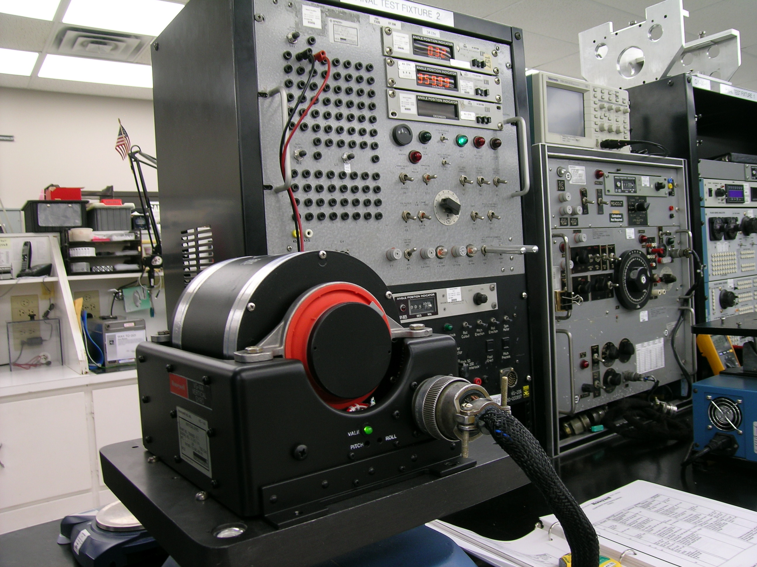
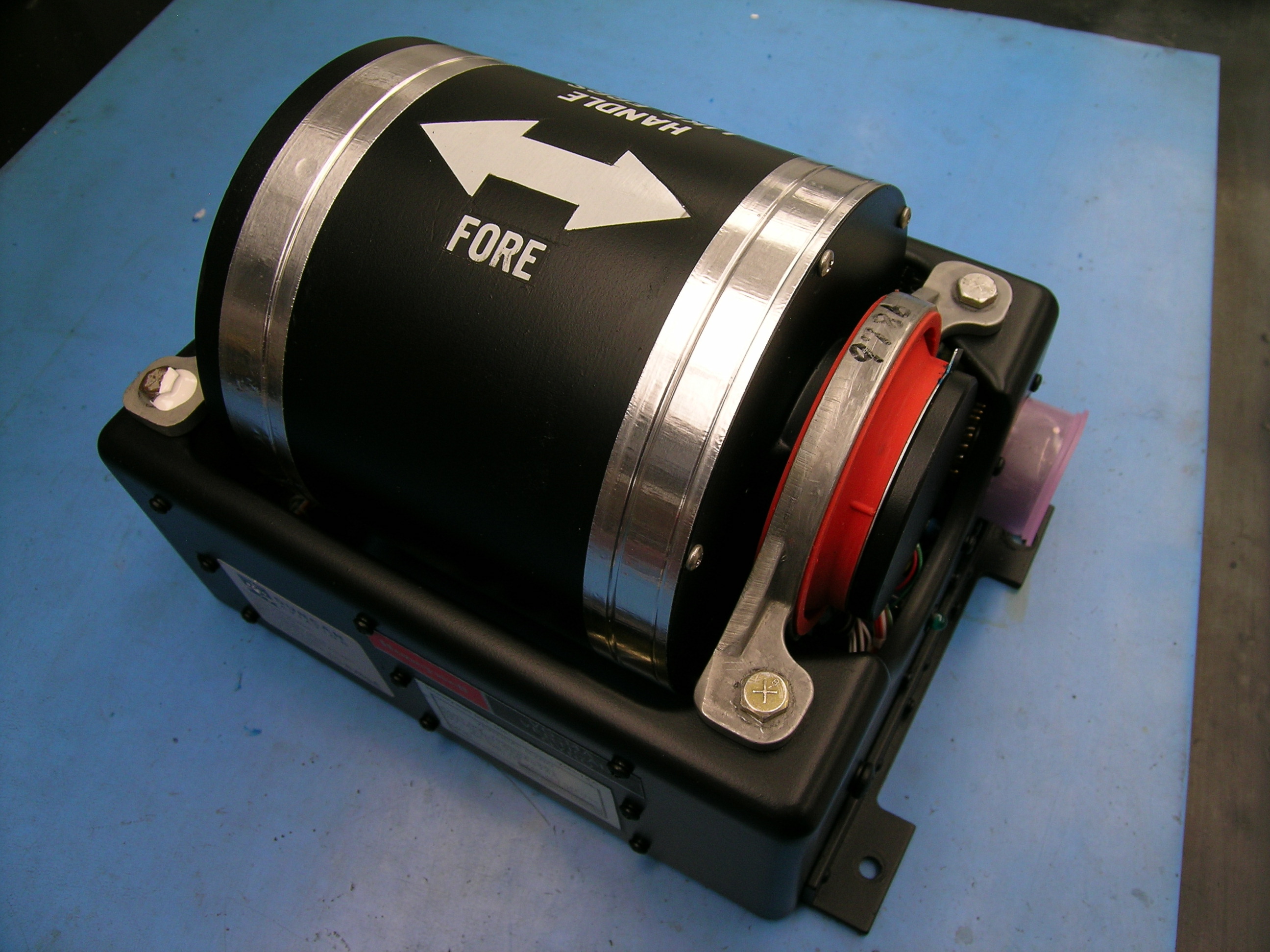
Why? Because if you don’t, this could happen!
And if it does…it could cost you lots of extra money. Here’s why.
Initial Function Test |
||
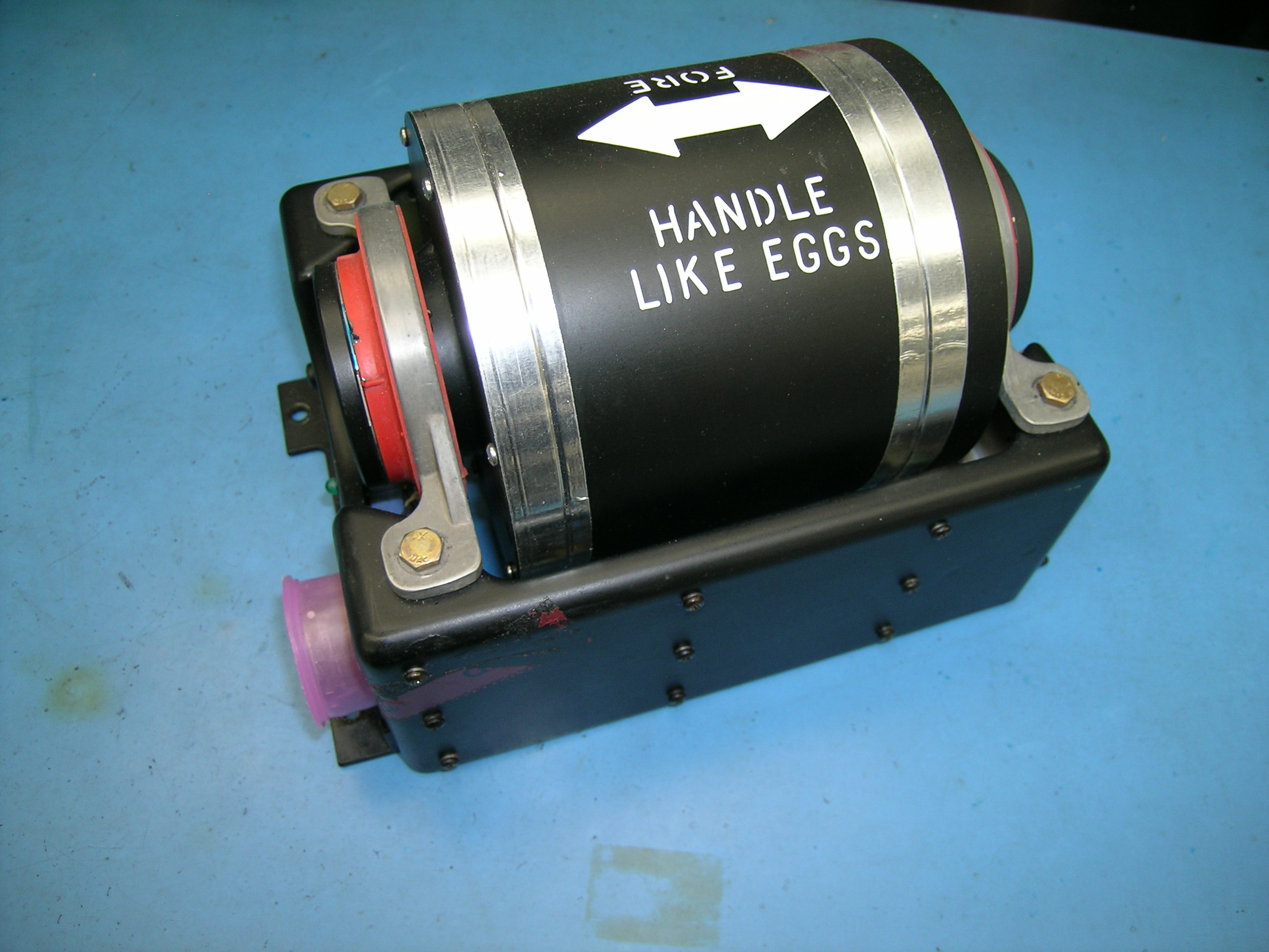 |
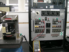
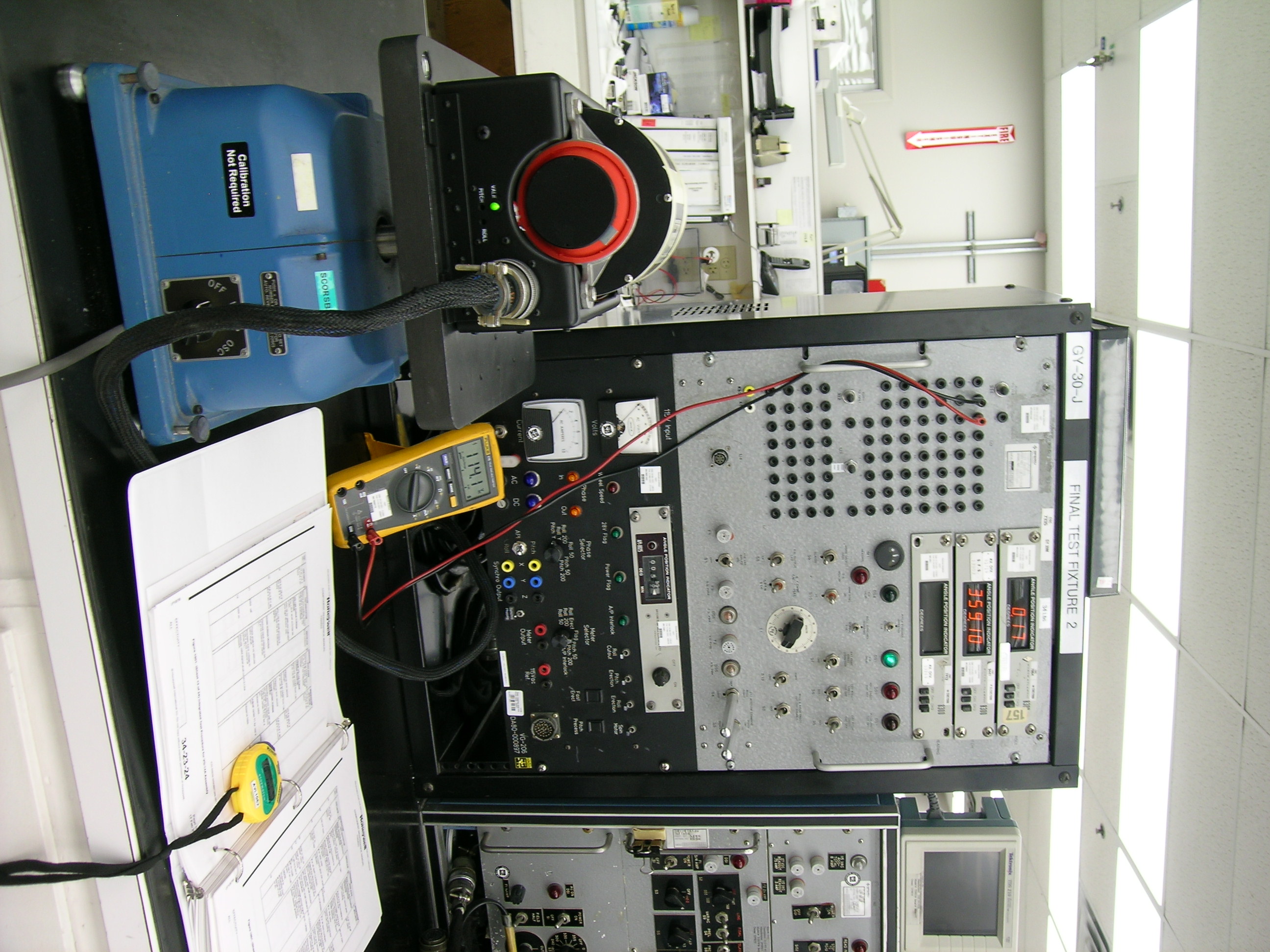
When your gyro arrives at Duncan Aviation’s component repair facility, it is put through a function test to duplicate the stated squawk. This initial function test provides us with a clear picture of the condition of the unit and a base line of information about the indicator, autopilot, and radar output. If the squawk is unable to be duplicated, the gyro is then placed into a freezer for additional environmental testing to determine the condition of the rotor. If the squawk is still unable to be duplicated, we will open the gyro after securing customer permission. |
|
Prep, Evaluation, & Customer Approval |
|
|
 |
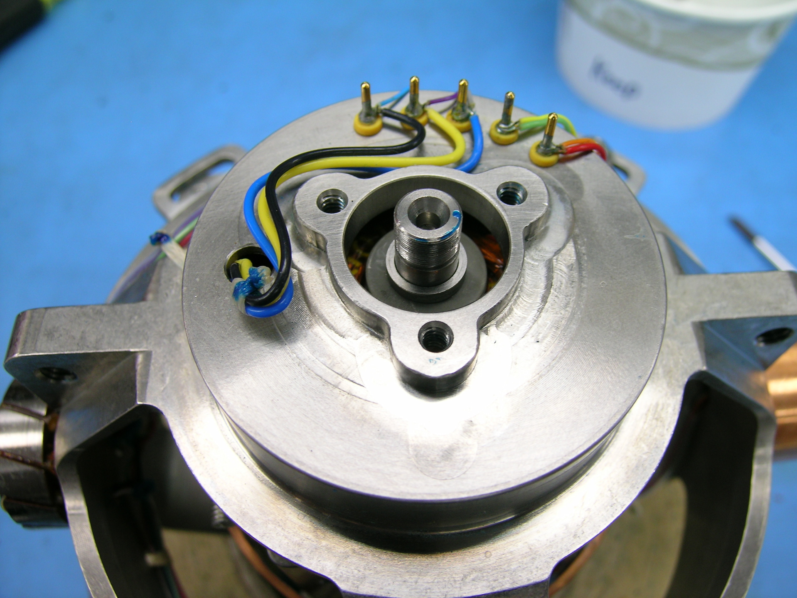
Before any repair or overhaul is performed, the condition of the unit and the following internal parts are assessed: Sensors, ohm out torquers, synchronizers, rotor, slip rings, brushes, and bearings. The results are communicated to our customers to make them aware of all squawks and/or damage sustained during shipping. (Read Critical Shipping Procedures When Transporting An Aircraft Gyroscope!) |
|
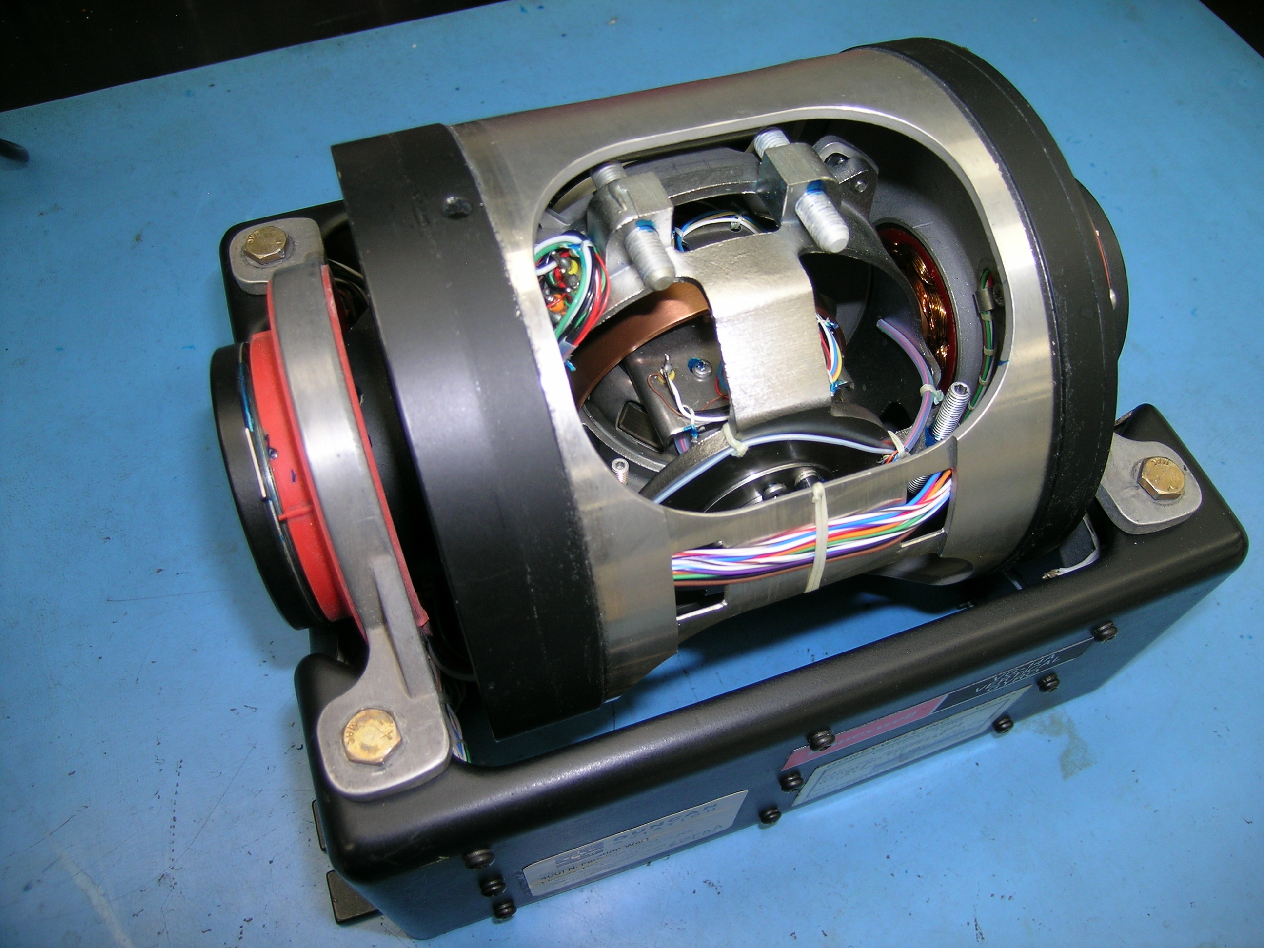
Disassembly and Inspection |
|
|
|
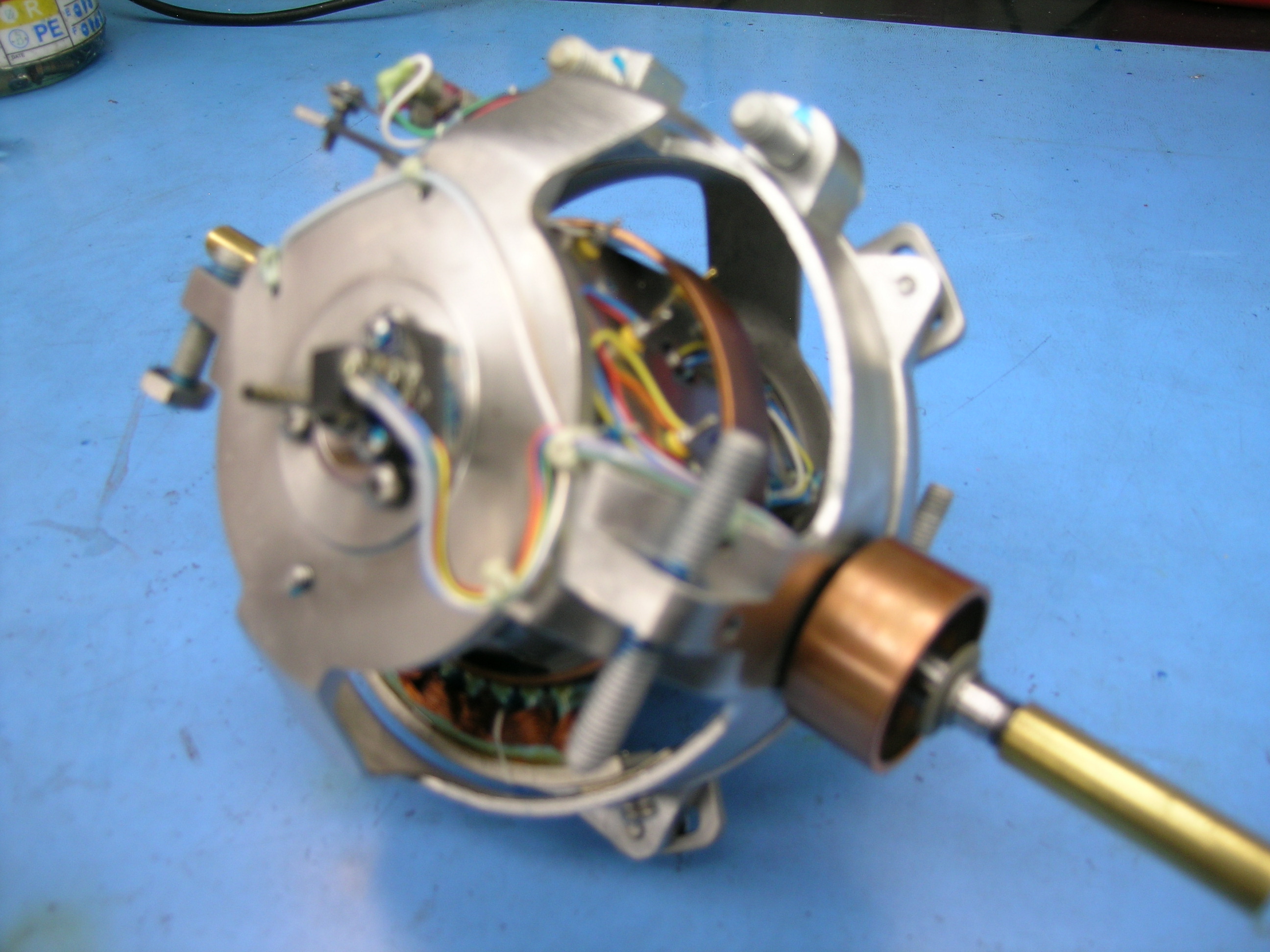
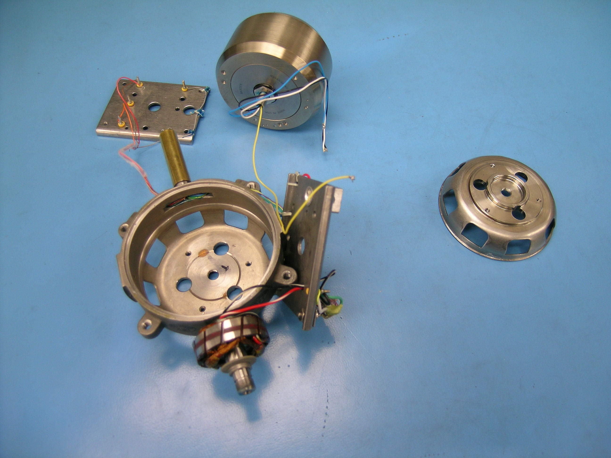
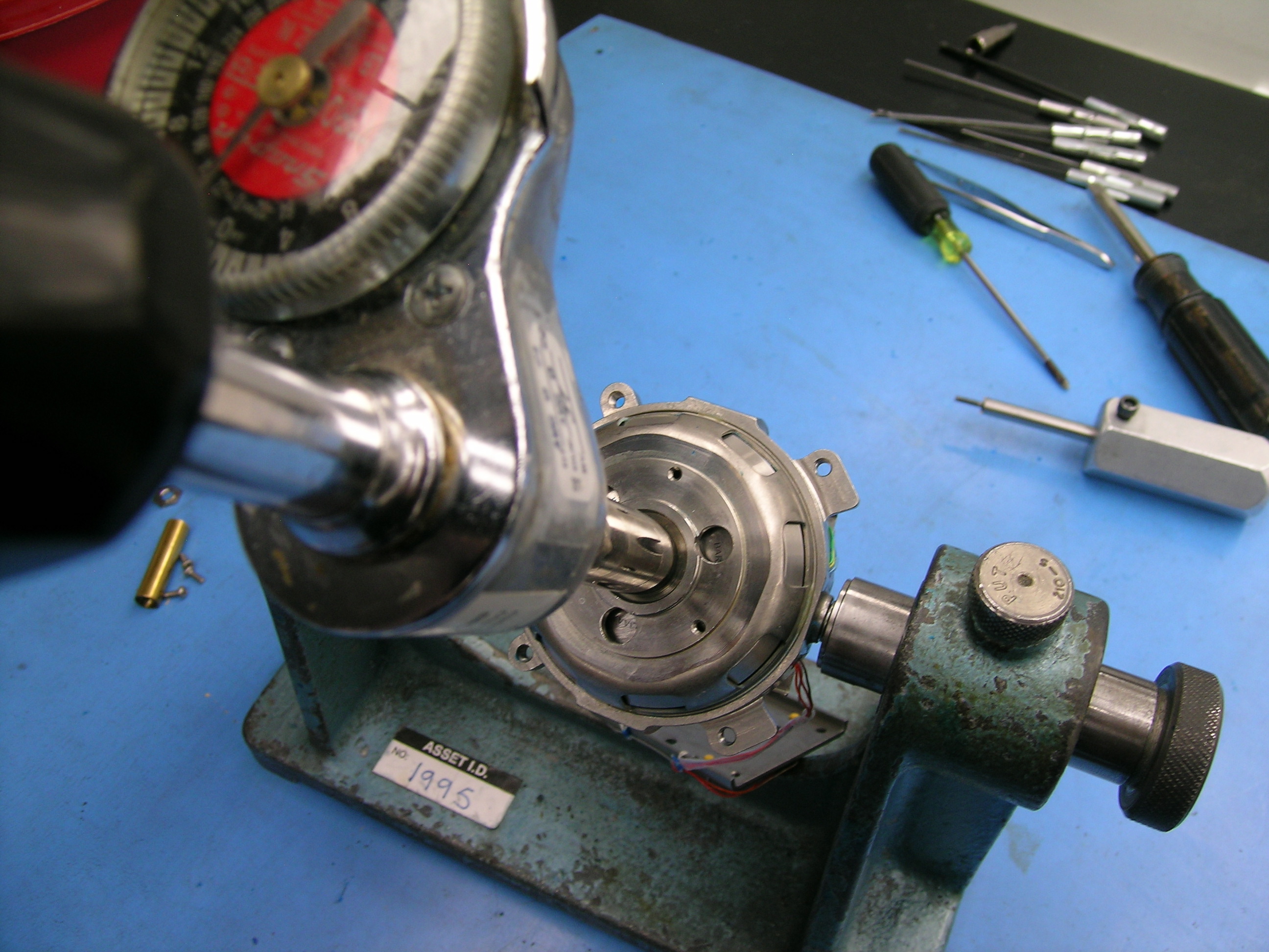
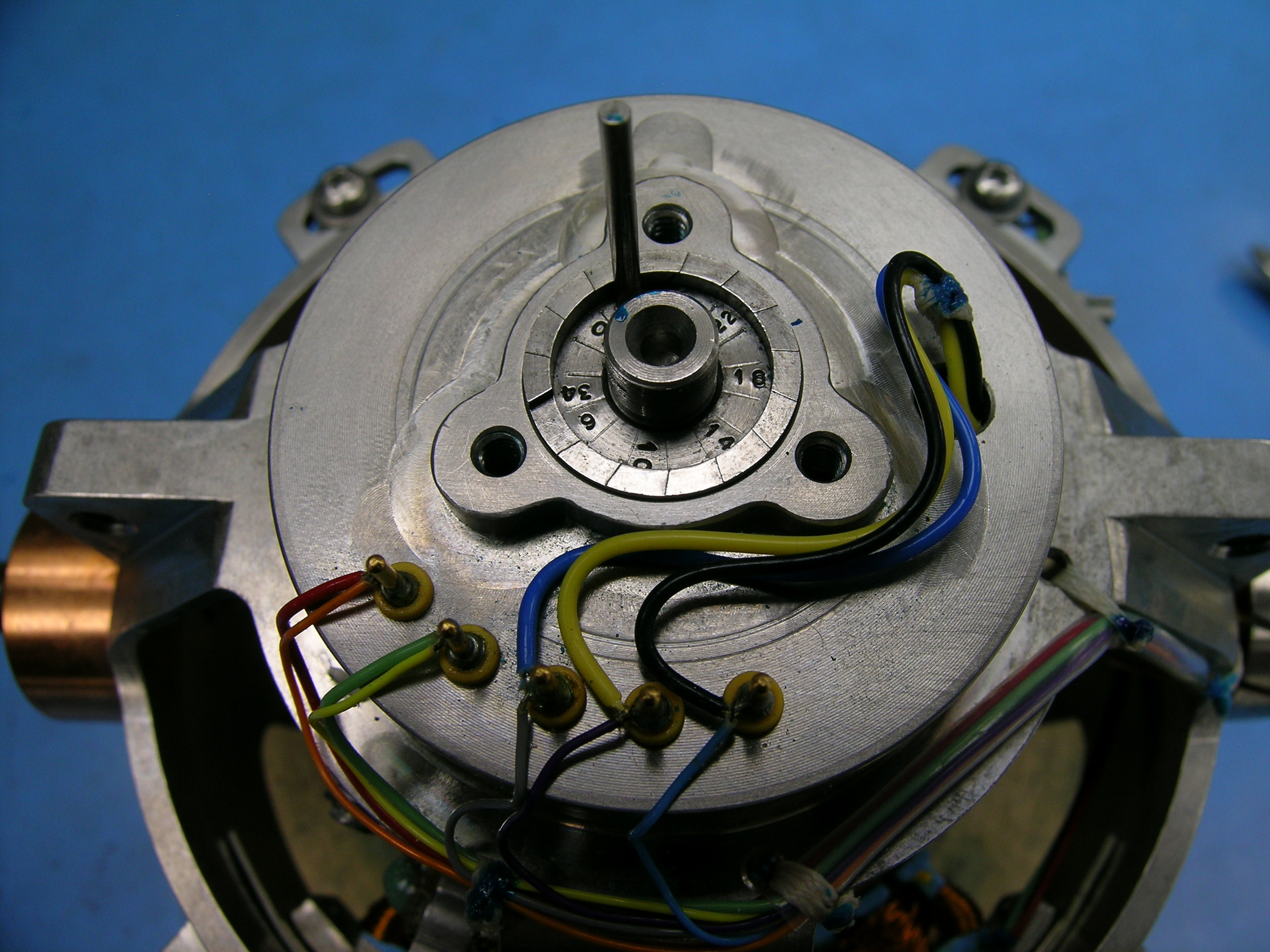
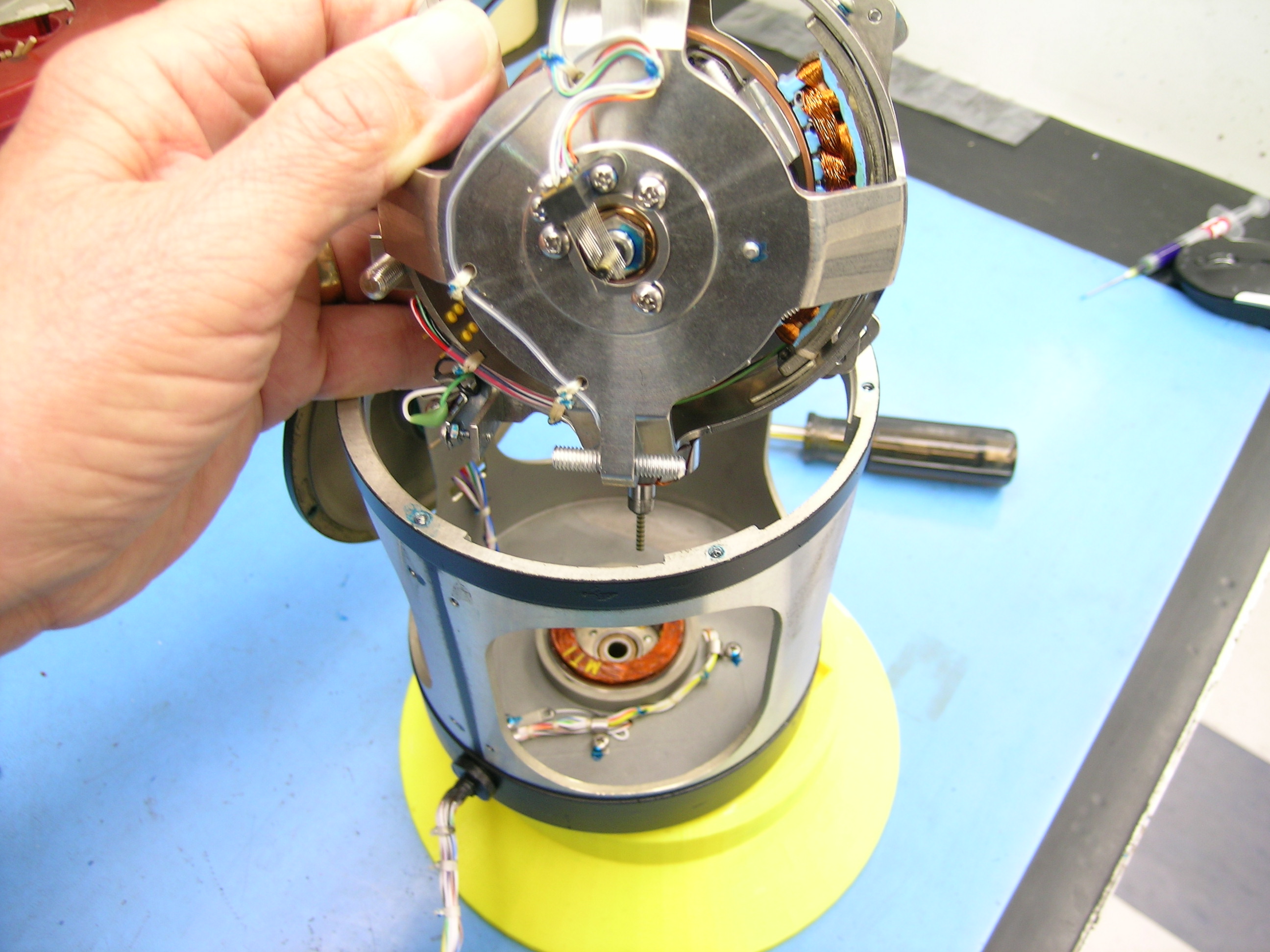
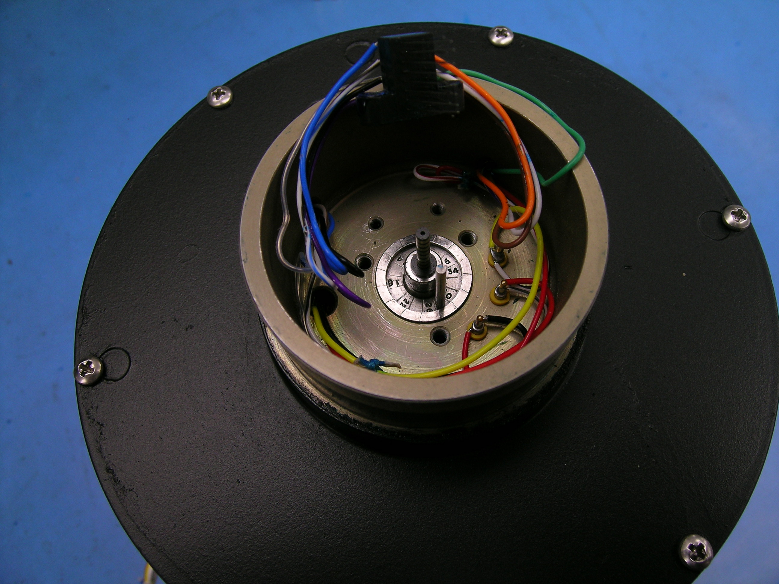
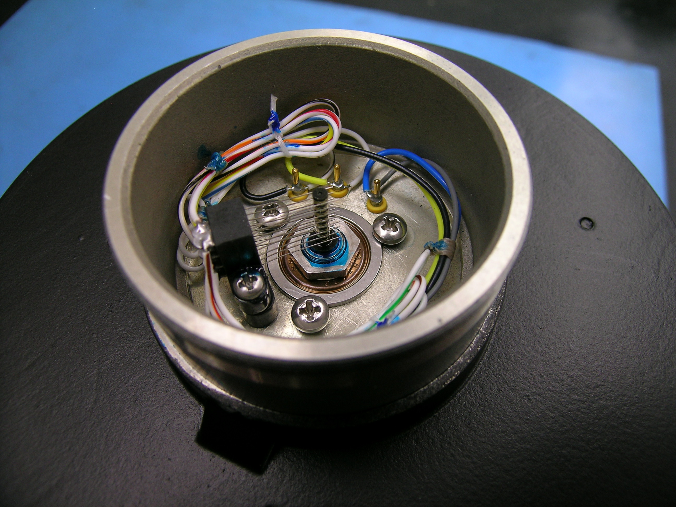
During the disassembly, every part is removed, cleaned, and inspected for damage and proper function. At the end of this stage, the gyro is reduced to its most basic components. The roll and pitch gimbals are pulled from the housing and disassembled by removing the torquer ring, hardware, plates, lower hemisphere, and rotor. The cover is reassembled and sent to paint. |
||
   |
||
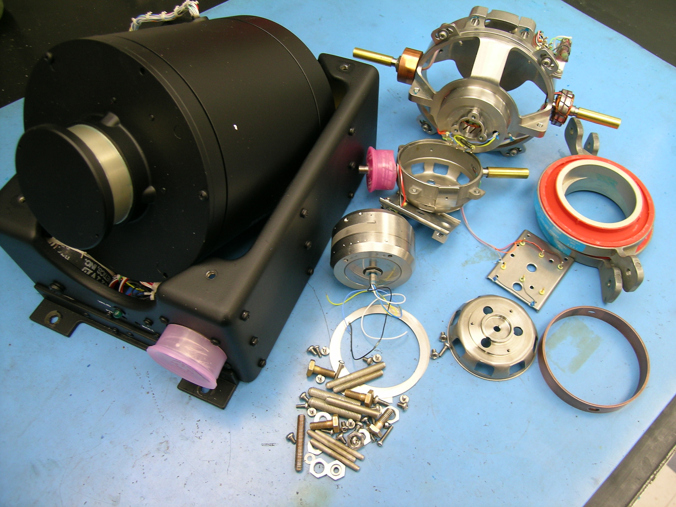 |
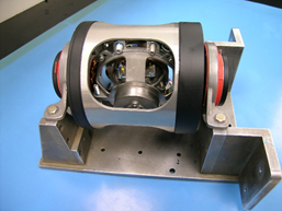
VG-401 disassembly is now complete. |
|
New Replacement Parts |
|
|
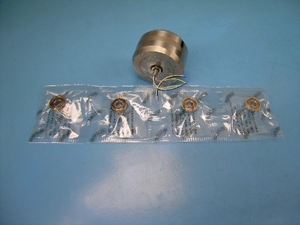 |
In a simple overhaul, where no additional parts are needed, the Honeywell Maintenance Manual calls for a new rotor and gimbal bearings. However, it is not uncommon for us to find it necessary to replace the leveling switch, slipring, or brushes. |
|
Assembly |
|
|
|
During the assembly phase of the overhaul, the process of taking everything apart is reversed to put back together. |
||
Pitch Gimbal Assembly |
|
|
 |
The rotor is positioned in the cage and the hemisphere is glued in place |
|
  |
With the plates attached, the pitch gimbal is placed in a balancing jig, the rotor is adjusted, and the nuts are tightened to torque specifications. |
|
  |
After the plates, roll torquer ring, and weights are installed and the wiring is hooked up and tied down, the pitch gimbal is balanced. |
|
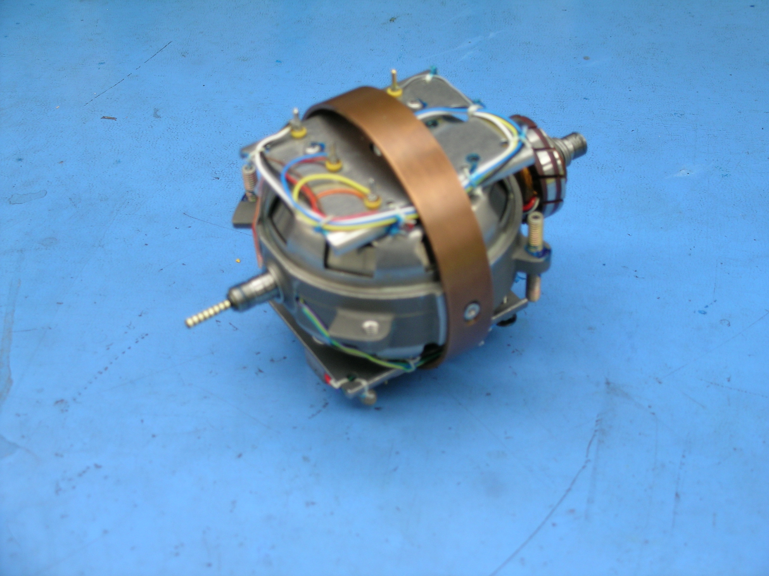
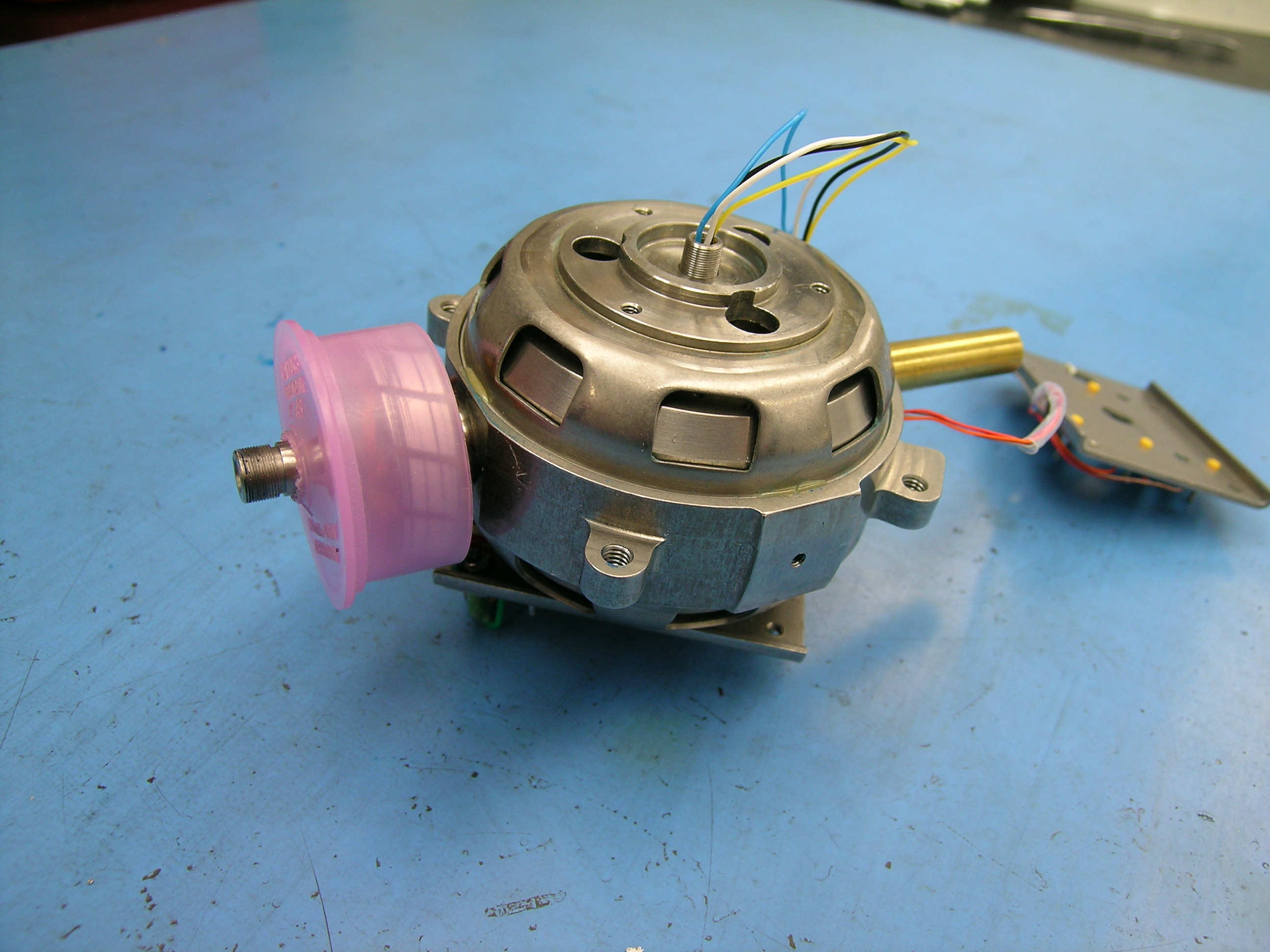
Roll Gimbal Assembly |
|
|
 |
The pitch gimbal is installed inside the roll gimbal. With a bearing installed and screws torqued, the gyro’s end play is adjusted. |
|
Adjusting The End Play |
|
|
|
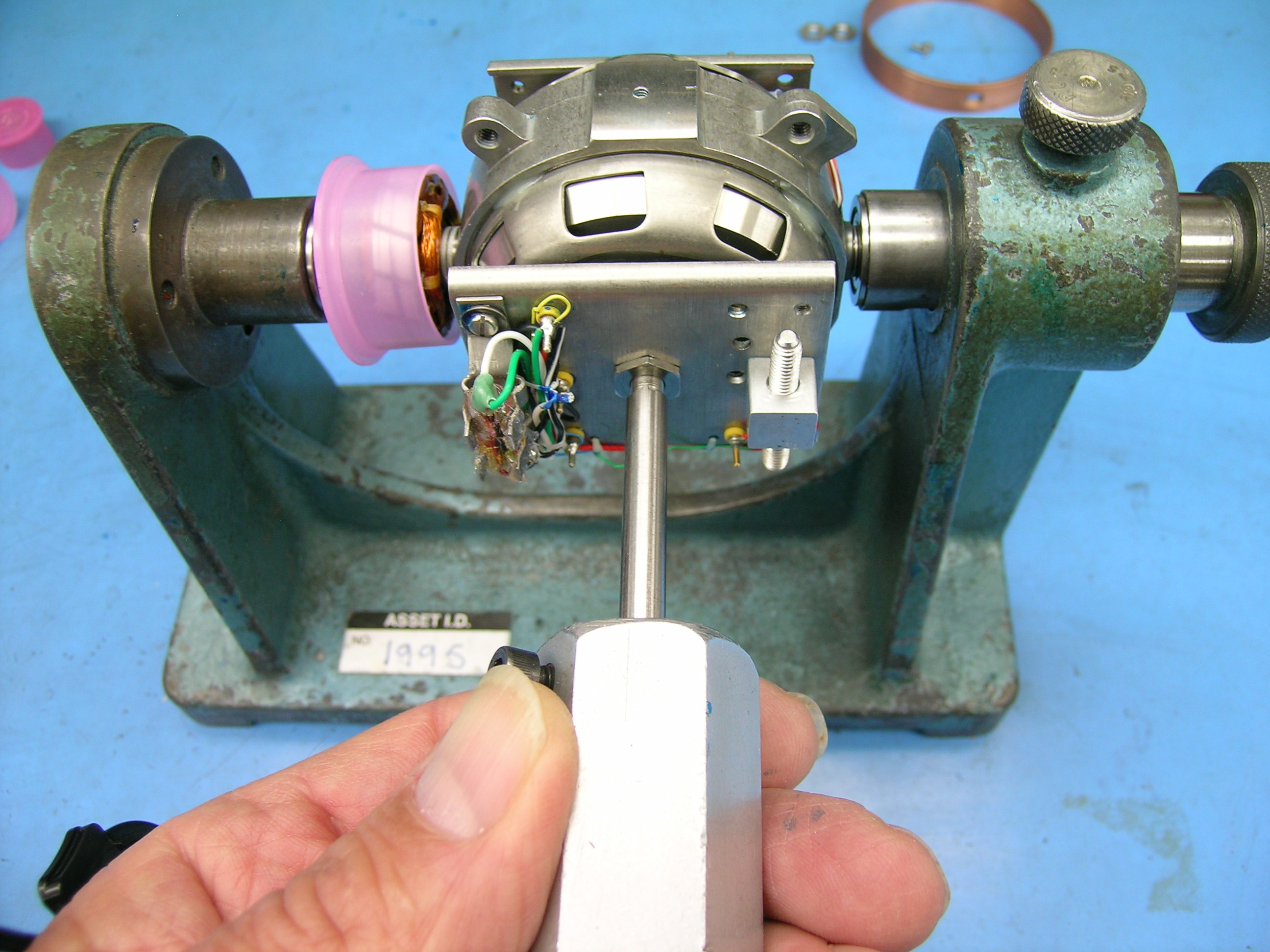
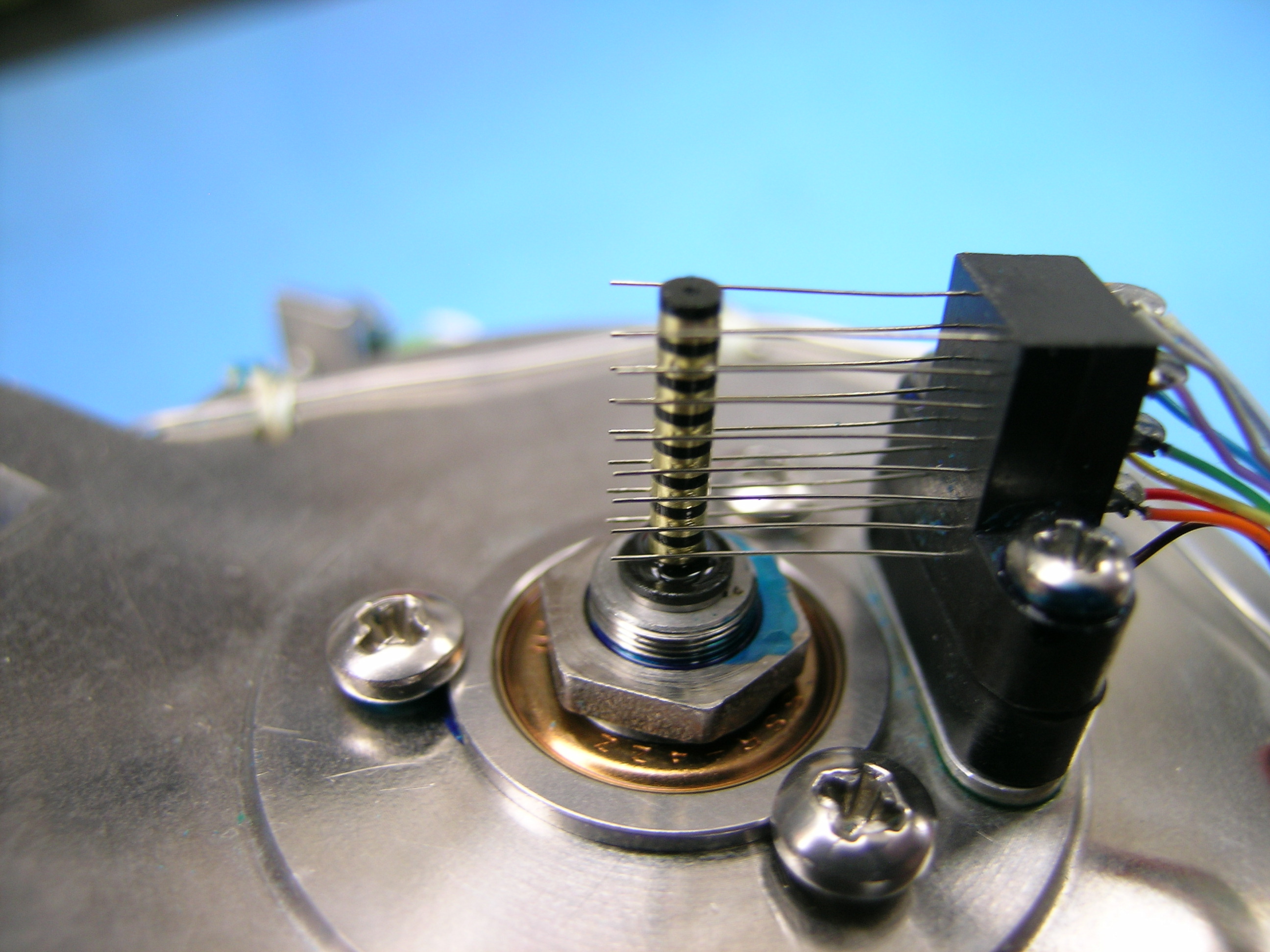
Adjusting the gyro’s end play is a critical step to proper operation. If there is too much play, or movement, around the pitch shaft, the gyro cannot be properly balanced. If the shaft doesn’t have enough movement, it could result in false instrument readings. A step plug is installed on both the pitch and roll gimbals. They are necessary to allow for the correct endplay to be obtained. |
||
 |
The step plug is first installed on the pitch gimbal and checked to make sure the correct number of shims are installed in the shaft. A bearing is installed with torqued screws. Slip ring nuts are tightened to proper torque allowing for greater endplay than specified. |
|
  |
The brush block is installed and alignment checked with the slipring The roll gimbal is mounted into the balancing jig. Weights are installed and adjusted. |
|
  |
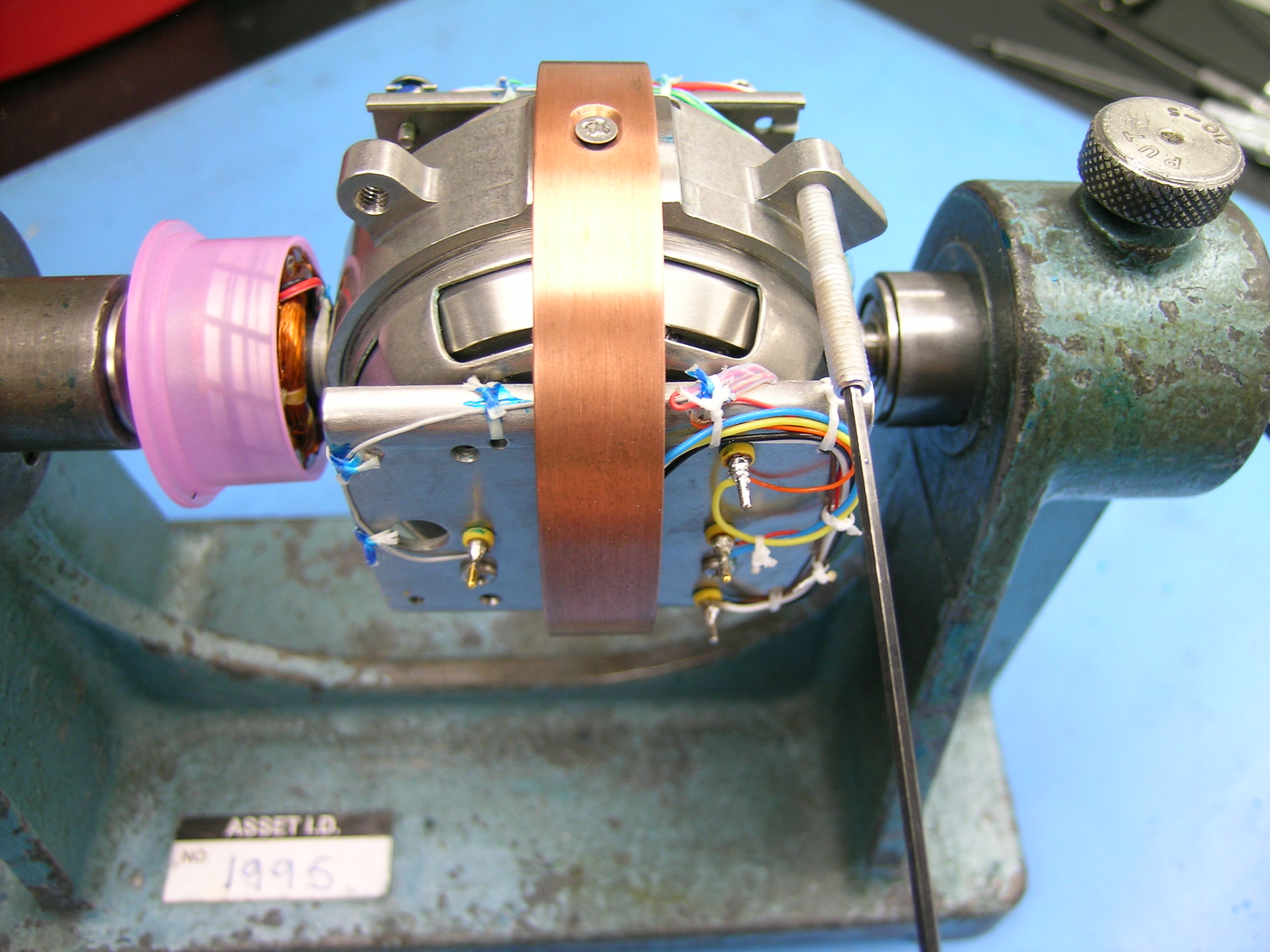
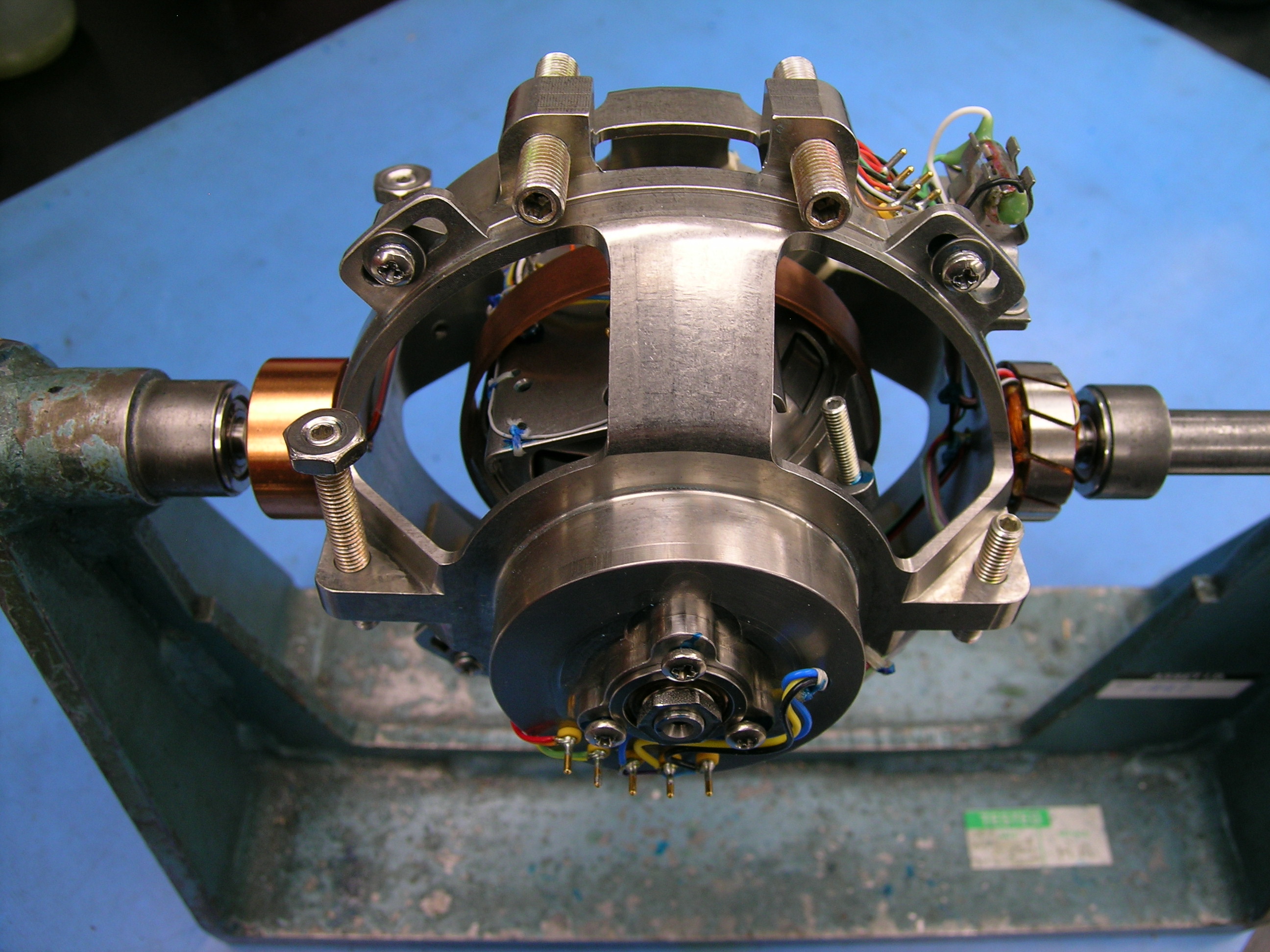
There are two ends to the housing. One is removable, the other is not. A bearing is installed on the non-removable end and torqued down with mounting screws. The roll gimbal is placed inside of the housing and the removable end is screwed in place and ready for the step plug. |
|
  |
Install brush blocks and oil with slipring lubrication. Installed strut mounts and end caps. The VG-401 is now ready for calibration. |
|
Calibration |
|
|
|
No overhaul is complete without proper calibration. Duncan Aviation performs the following calibrations: |
||
 |
|
|
 |
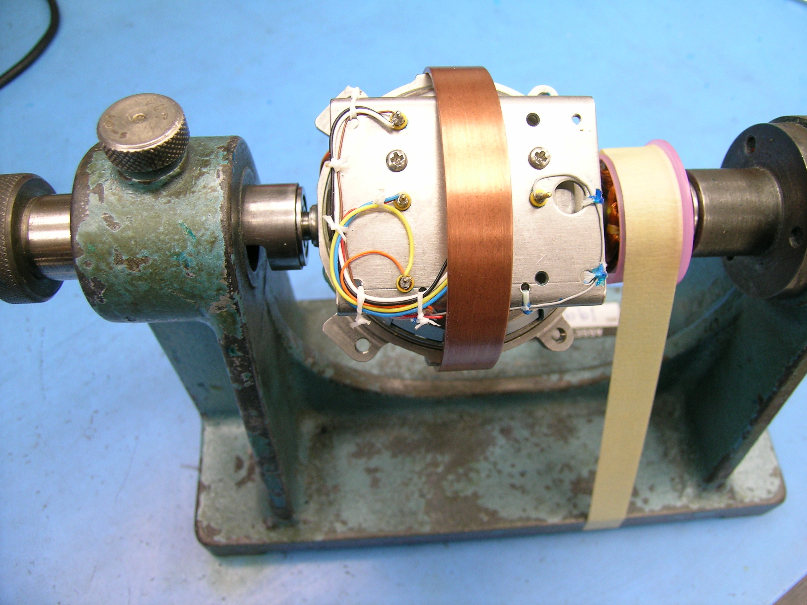
After all of the calibration tests, the cover is replaced and taped, mounted on the base, and tested again. It now heads to the freezer for additional environmental testing. |
|
Final Testing |
|
|
 |
The unit is completely disassembled again and is put through a rigorous final quality inspection. After the final reassembly, it is taped up with the Honeywell aluminum tape and ready for the final test. |
|
 |
After the final test, warranty stickers are applied and the unit is returned to service. It is then boxed properly and shipped back to the customer. |
|
July 2026
July 2026
July 2026
June 2026
June 2026