This is a brief update on the current engine Service Bulletins for the Pratt & Whitney PW308C engine that can be accomplished on in-service engines.
Effectivity is Build Spec (BS) 1047 & 1238 only for engines up to and including serial number PCE-CF0563. If you receive an ECTM Alert for engine performance degradation, this would be one of the first things to look at.
If this SB (Service Bulletin) has not yet been complied with, remove the valve and inspect the drain Transfer Tube packings. If the packings are gone, brittle or severely deteriorated, this will cause not only a P3 bleed leak but also allow the Transfer Tube to work or chatter.
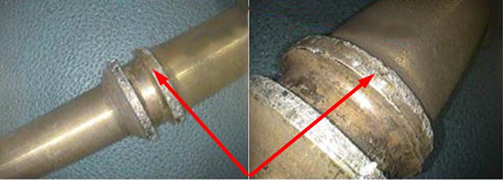
Upper P3 Air Tube Opening: Below is the upper packing groove for the P3 Air Tube at disassembly. These pictures show fragments of the packing intact.

This chatter could cause damage to the engine that would require Pratt & Whitney MRT support to repair on-wing. The pictures show the fretting caused by the missing packings and the Transfer Tube working. Please refer to SB 72-26355 to fix this condition.

P3 Tube lower sealing area

P3 Air Tube power packing groove. Packing was missing at disassembly and tube is fretted.
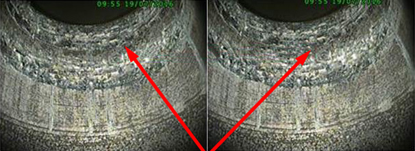
A borescope inspection for Abradable splatter on the 4th Rotor Drum should be performed at 2,400 hours TSN (Time Since New) or TSO (Time Since Overhaul) and every 400 hours thereafter. This is the spacer or drum between the 4th Stage Axial Compressor and the Centrifugal Compressor. Radial splatter marks will begin to appear as white streaks on the drum when the Abradable material is delaminating (photo below left). The photo below right shows a normal indication. Any indication of splatter needs to be reported to the Pratt & Whitney Customer support portal, CFirst for further disposition.
Engines that surge, whether during acceleration or deceleration, may lead you to perform this inspection. The disposition may require an engine removal.

Removal of the PW308C LP Turbine Module borescope plug has been an issue during scheduled borescope events. While removing the plug the 10/32 bolts (item 1 in the picture below) will either break or the inserts in the Turbine Case will spin before the bolt is free of the run on torque of the self-locking device.
Previously, this required the engine to be removed so that the LP Turbine Module could be removed to repair. There is a SB now (SB 72-26322) that has shown SOME success where this repair can be done on wing. Although not 100% successful this may still require the engine to be removed.

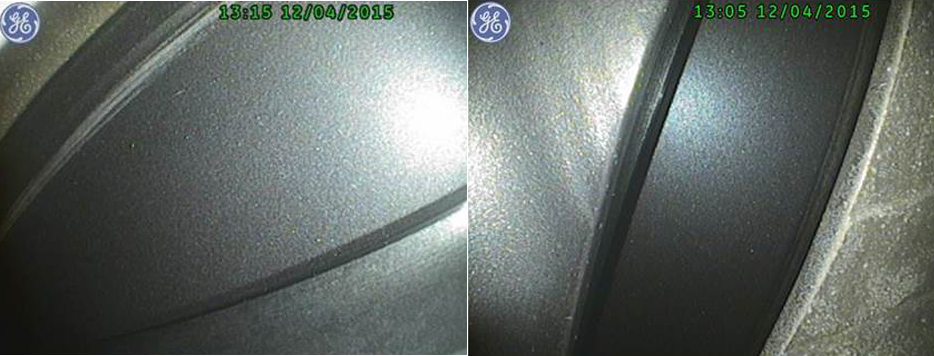
This SB is applicable to Falcon 2000EX, EAsy, LX, LXS, DX & S model aircraft. This SB requires a borescope inspection of the Piccolo Tube that can be done on-wing. Pictures below show the perforation holes blocked by what the SB calls manufacturing residue. Dassault provides a tool to the MROs to remove this residue. Included in the kit is a go/no-go gauge to check the opening of the Piccolo air inlet. Dassault will need to be contacted for disposition if the test fails.

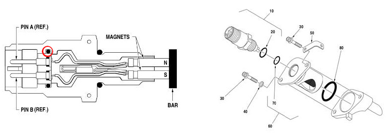
If you experience intermittent chip detector indications, follow the fault isolation to look at the sensors. Make sure to inspect the cannon plug and the sensor plug receptacle for moisture. This moisture may be oil leaking through the sensor casing causing the intermittent indication. Through visual inspection verify the plug receptable is dry and clean. Additionally inspect the potting material at the base of the pins for cracks. It’s recommended to replace if noted.
Oil will bypass this packing or through cracks in the potting material into the cannon plug receptacle. (See drawings below).

December 2025
May 2025
March 2025
March 2025
January 2025